2. Case 1 - FBF Using next-ip / next-interface Actions
RLI 14784 introduces two new terminating actions in firewall filters:
- next-interface
routing-instance - next-ip
routing-instance
Note: IPv6 is also supported via the
next-ip6variant.
These actions are terminating, meaning there's no need to include an explicit accept statement. Both are supported under the inet and inet6 families.
The typical usage for these actions is illustrated below:
1 2 3 4 5 6 7 8 9 10 11 12 13 14 15 16 17 18 19 20 21 22 23 24 25 26 27 28 29 30 31 | |
2.1. Overall Behavior
When a packet matches a term using one of the below actions:
next-interface: The system verifies the operational state of the specified interface, along with the availability of an ARP (or ND for IPv6) entry for the next-hop. If arouting-instanceis specified, the interface lookup is performed within that context. If all conditions are met, the packet is forwarded via the corresponding egress IFL. If the interface is down or unresolved, the packet is dropped.next-ip(6): The IP address specified innext-ipornext-ip6is not automatically resolved. On Ethernet interfaces, reachability must be ensured through routing—either via dynamic protocols or static routes. If a matching route (exact or more specific) is found, the packet follows the next-hop associated with that route. If no matching route exists, the packet is rejected.
Read carefully: if next-ip address becomes unreachable the default approch is to point the traffic to the default reject next-hop. Traffic rejected are thus punted to the RE for sending back an ICMP unreachable. However, no worries about "overloading" the internal host-path. Indeed, there is a default DDOS protection policer that will rate-limit those rejected punted packets to 2Kpps. We will see later, how to handle this behavior in case you want silencly discard the packet when next-ip address becomes unreachable.
2.2. Caveats
Known limitations include:
- Supported only for ingress filtering
- No fallback mechanism (The EVO exact match option is not supported)
- Not supported on LT interfaces
2.3. Example 1 - topology
The diagram below illustrates the topology used to demonstrate simple FBF on an MX platform.
The Device Under Test (DUT) is an MX480 equipped with an MPC10E line card.
This simplified setup represents a typical DCI router connected to an IP Fabric, providing access to remote resources via two distinct paths:
- A quality path through an MPLS/SR core network, and
- A best-effort path via a direct peering or transit (PNI) connection.
By default, remote resources are reached via the direct PNI link. The DUT hosts an Internet VRF, which is also used by a remote ASBR in the same AS. This ASBR advertises "public/remote" prefixes to all PE routers—including the DUT—via L3VPN (inet-vpn). The direct PNI interface is also part of the Internet VRF.
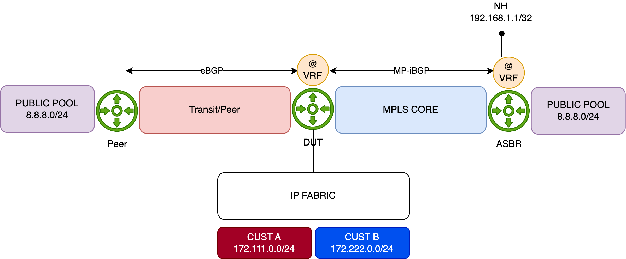
For demonstration purposes, the remote resource is simulated using the public prefix 8.8.8.0/24. This prefix is preferred by default via the direct PNI, with a backup path available through the MPLS/SR core:
1 2 3 4 5 6 7 8 9 10 11 | |
The IP Fabric serves two customer types—A and B—represented by IP prefixes 172.111.0.0/24 and 172.222.0.0/24, respectively. The DUT exchanges IP traffic with these customers directly.
This is just a table for test:
| PFE COMPLEX | Port Number | 10GE mode | 40GE or 100GE modes |
|---|---|---|---|
| EA ASIC 0 | 0 | xe-x/1/0:[0..3] | et-x/1/0 |
| 1 | xe-x/1/1:[0..3] | et-x/1/1 | |
| 2 | xe-x/1/2:[0..3] | et-x/1/2 | |
| 3 | xe-x/1/3:[0..3] | et-x/1/3 | |
| EA ASIC 1 | 4 | xe-x/1/4:[0..3] | et-x/1/4 |
| 5 | xe-x/1/5:[0..3] | et-x/1/5 | |
| 6 | xe-x/1/6:[0..3] | et-x/1/6 | |
| 7 | xe-x/1/7:[0..3] | et-x/1/7 | |
| EA ASIC 2 | 8 | xe-x/1/8:[0..3] | et-x/1/8 |
| 9 | xe-x/1/9:[0..3] | et-x/1/9 | |
| 10 | xe-x/1/10:[0..3] | et-x/1/10 | |
| 11 | xe-x/1/11:[0..3] | et-x/1/11 |
Table 1: Interface Naming of the 6xQSFPP PIC
Initial Configuration
Below is the initial configuration for the DUT's Internet VRF, kept simple for clarity:
- The DUT receives customer prefixes via eBGP from the peer group FABRIC.
- It receives public prefixes from the peer ASBR via eBGP, with an import policy (PREF) setting a high local preference to make this path the best.
- Two interfaces belong to the Internet VRF—one facing the IP Fabric, and the other towards the PNI peer.
- The DUT also connects to the MPLS core, running IS-IS with Segment Routing for label distribution.
1 2 3 4 5 6 7 8 9 10 11 12 13 14 15 16 17 18 19 20 21 22 23 24 25 26 27 | |
Configuration of FBF
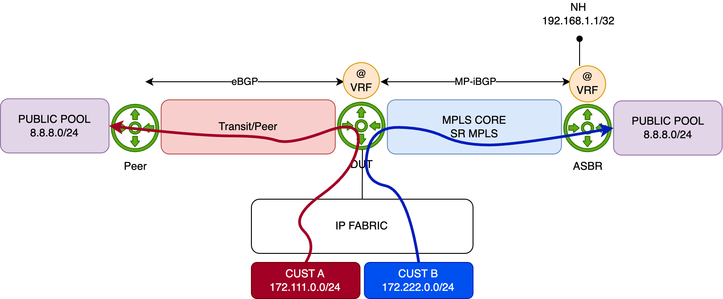
Using the previous topology, we demonstrate a typical FBF use case leveraging the next-ip action (the same behavior applies to next-ip6 and next-interface).
The objective is to override the default forwarding behavior—where traffic exits via the direct PNI interface—for traffic sourced from Customer B (172.222.0.0/24). Instead, traffic from this prefix should be redirected through the MPLS backbone, targeting the remote ASBR to reach the public resource.
Traffic from other sources will continue to follow the default “best path,” which remains the direct PNI link.
The diagram below illustrates this behavior:
How will we achieve this?
The configuration is straightforward. First, we define a firewall filter that matches the source prefix 172.222.0.0/24, and apply the next-ip action to redirect traffic.
Which next-ip address should be used?
That depends on the network design. In this example, we target the loopback address of the remote ASBR, which is advertised via BGP (L3VPN). As shown below, the route to this loopback is reachable through the MPLS/SR core via an established tunnel:
1 2 3 4 5 6 7 8 | |
Now let's configure the FBF filter. Since we're operating within a VRF context, the routing-instance parameter is specified along with the next-ip action—this ensures that the next-hop lookup is performed in the correct FIB instance.
An additional term is included to match all remaining traffic, allowing it to follow the default forwarding behavior.
1 2 3 4 5 6 7 8 9 10 11 12 13 14 15 16 17 18 19 20 21 | |
Before applying the filter, we'll generate traffic from Customer A and Customer B. To distinguish between the two flows, we configure the traffic rates as follows:
- Customer A: 1000 packets per second (pps)
- Customer B: 5000 packets per second (pps)
Both customers will send traffic toward the 8.8.8.0/24 prefix.
We now start the traffic and verify the statistics on the PNI interface:
1 2 3 4 5 6 7 8 9 | |
At this point, all traffic is following the best active path—via the PNI interface—to reach the 8.8.8.0/24 prefix.
Another table just for test:
| PFE COMPLEX | Port Number | 10GE mode | 40GE or 100GE mode |
|---|---|---|---|
| EA ASIC 0 | 0 | xe-0/0/0:[0..3] | et-0/0/0 |
| 1 | xe-0/0/1:[0..3] | et-0/0/1 | |
| 2 | xe-0/0/2:[0..3] | et-0/0/2 | |
| 3 | xe-0/0/3:[0..3] | et-0/0/3 |
Table 2: Interface Naming of the 4xQSFPP PIC
We now apply the FBF filter in the ingress direction on the interface connected to the IP Fabric:
1 2 3 4 5 | |
And then, recheck the PNI interface statistics:
1 2 3 4 5 6 7 8 9 10 | |
The FBF filter is functioning as expected. Only Customer A traffic continues to follow the default best path toward 8.8.8.0/24 via the PNI interface.
Next, we check the statistics on the core-facing interfaces to confirm that Customer B traffic is being properly redirected through the SR/MPLS tunnel as intended by the FBF configuration:
1 2 3 4 5 6 7 8 9 10 | |
Everything looks good! To demonstrate that there is no fallback mechanism with next-ip-based FBF, we'll remove the loopback (192.168.1.1/32) announcement from the ASBR. As a result, the DUT will no longer have a route to the loopback, and the traffic will be dropped:
1 | |
This means that traffic from Customer B should be dropped, which is exactly what we observe. As shown below, there is no longer any traffic on the Core interface, and Customer A traffic continues to flow through the PNI port.
1 2 3 4 5 6 7 8 9 10 11 12 13 14 15 16 17 18 19 20 21 | |
As discussed earlier, the default action when next-ip address becomes unreachable is to redirect traffic to the reject next-hop. Above, we issue a show route of the next-ip address and nothing was return as expected. Just now issue the show route forwarding-table:
1 2 3 4 5 | |
The route points to reject next-hop in the FIB. As said, the next-hop will punted the packets to the RE for further processing (ICMP unreachable). As also mentioned those punted packet are rate-limited by the ASIC to 2kpps. We can verify this behavior, by checking the DDOS protection statistics for the "reject" protocol:
1 2 3 4 5 6 | |
We saw our 5K of Customer B traffic before being rate-limited. Issue the "violation" check command to see the rate-limit value of 2K pps:
1 2 3 4 5 6 7 | |
So it means our RE will received a maximum of 2K rejected packets and will generate 2K ICMP unreachable packets in reply. Just check our port connected to the IP Fabric and oh ! Suprise 2Kpps in output. These are our ICMP unreachable sent out back to the Customer B.
1 2 3 4 5 6 7 8 9 10 | |
How we can avoid that?
The easiest solution is to have in your FIB always a last resort route entry, that could be discard but why not a fallback path to route the next-ip address. In our case, if 192.168.1.1 deaseappers, we may want:
- to not reject/discard the traffic but move back to the PNI interface. For that we need to configure a static route pointing to PNI peer, with a higher preference as a backup path for 192.168.1.1. Let's do simply add this static route in our VRF and check just after the commit the statistics of our PNI interface to see if all our 6K pps (A+B traffic) are forwarded back:
1 2 3 4 5 6 7 8 9 10 11 12 13 14 15 16 | |
- or to silently discard the traffic. In this scenario we can create a static route with higher preference pointing to discard next-hop. In our case, I've just added a default discard route in the VRF. so, if 192.168.1.1/32 is not announce anymore, the lookup of the next-ip address will fall back to this default discard instead of matching the default reject. Let's remove the previous static route and add the new default one:
1 2 3 4 5 6 | |
So, with this last configuration, our Customer B traffic should be now silently discared and we shouldn't observe DDOS protocol violation and ICMP unreachable traffic:
1 2 3 4 5 6 7 8 9 10 11 12 13 14 15 16 17 18 | |
2.4. PFE analysis
Now, let’s re-announce the 192.168.1.1/32 prefix and examine how the FBF filter is applied on the PFE. Begin by running the following command to access the PFE CLI:
1 | |
Next, list all the filters available on the linecard:
1 2 3 4 | |
Now resolve the token index 2875 to display the filter’s program:
1 2 3 4 5 6 7 8 9 10 11 12 13 14 15 16 17 18 19 20 21 22 23 24 25 26 27 28 | |
The above output shows the filter program optimized by the Firewall Filter compiler. To display the actual program pushed into hardware, use the following PFE commands:
1 2 3 4 | |
Then, run this second command using the Token ID 5424, retrieved from the previous step:
1 2 3 4 5 6 7 8 9 10 11 12 13 14 15 16 17 18 19 20 21 22 23 24 25 26 27 28 29 30 31 32 33 34 35 36 37 38 39 40 41 42 43 | |
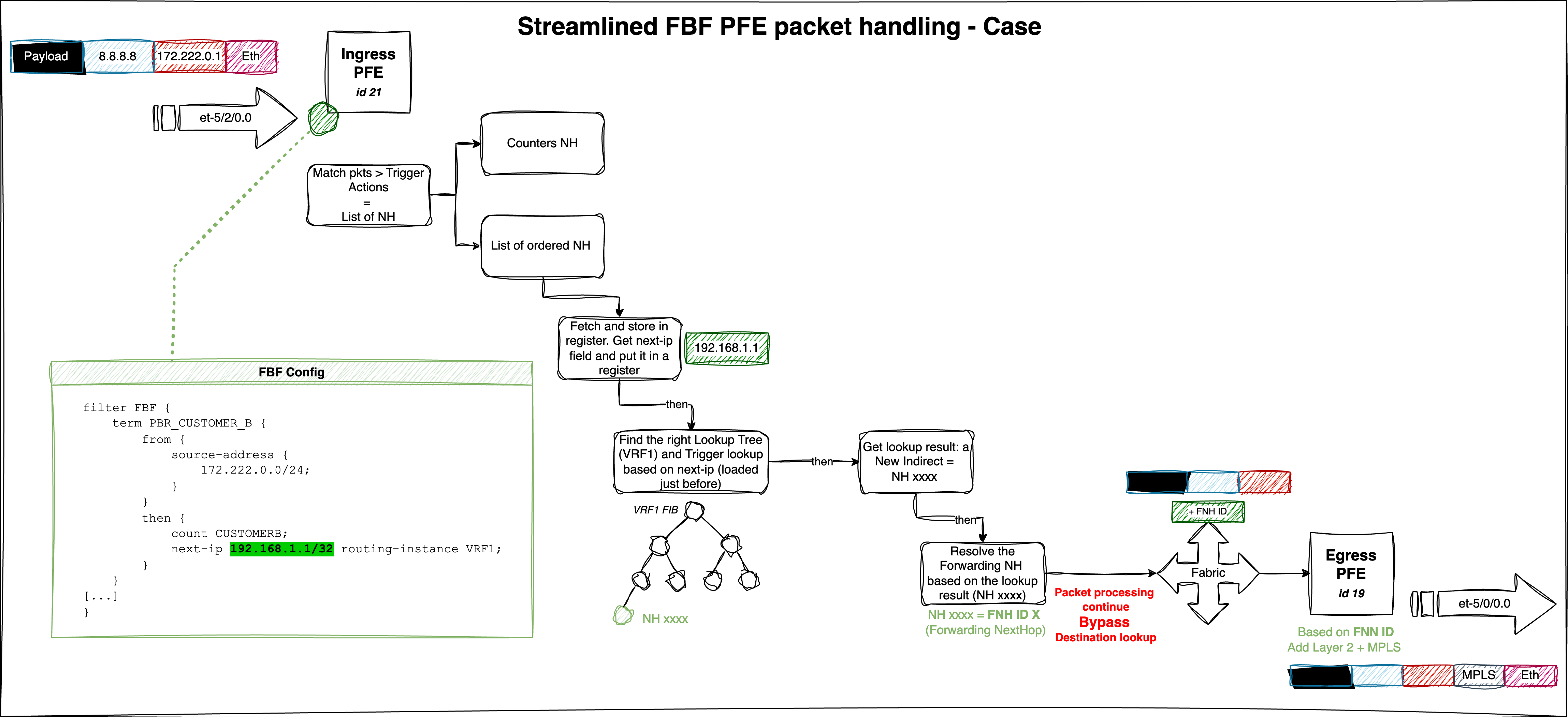
Pick the JNH dword corresponding to the next-ip action 0x201282240000000c (line 40), and decode it:
1 2 | |
UcodeNH will run a micro-code sequence. Here, it is an indirection to a virtual address found in the Next field. To read the data at 0x4a089, run:
1 2 | |
This returns two key values:
- Paddr (physical address):
0x104a089 - Data read:
0x0812659400040000
Note: To read a physical address, use
show pread paddr xxx.
Since the value is a JNH word, decode it again. This time it reveals a CallNH, a list of ordered next-hops (when mode=0):
1 2 3 4 5 6 7 | |
Now decode each action (excluding the fifth one, which is outside the scope of this article):
- The first is a
ModifyNH, which modifies local memory — in this case, resetting the encapsulation length:
1 2 3 | |
- The second and third entries are BitOpNH actions, performing operations on specific data:
1 2 3 4 5 | |
These actions extract the next-ip address from local memory in two steps:
- First, we fetch
49320(0xC0A8 = 192.168) - Then, we fetch
257(0x0101 = 1.1)
Combined, we recover the next-ip address from our FBF filter: 192.168.1.1. This is a "key" that will be used for further processing (route lookup).
- The fourth NH in the list
0x1810318200200008is a KTREE structure used for route lookup:
A KTREE is Juniper’s implementation of a binary structure known as a Patricia Tree.
1 2 | |
To dump the full KTREE, use:
1 2 3 4 5 6 7 8 9 10 11 12 13 14 15 16 17 18 19 | |
This KTREE acts as the FIB for our VRF1 instance. For instance, traffic hitting the 192.168.1.1/32 prefix is redirected to the action identified by the JNH word 0x08129a1800000000, pointing to a CallNH:
1 2 3 | |
This value (0x20129af00000000c) is another UcodeNH indirection:
1 2 | |
To follow the indirection, read the next-hop at 0x4a6bc:
1 2 | |
Once again, decode the JNH word retrieved from the virtual memory address — it points to another CallNH list:
1 2 3 | |
Decode the final NH word 0x11c0000000026c14:
1 2 3 | |
We’ve reached the final forwarding action — setting the forwarding NH index via the NH Token. Here, the token 0x26c corresponds to the NH ID from our route lookup.
To get more info on this next-hop:
1 2 3 | |
Perfect — this confirms that the traffic is forwarded via the correct path: our core-facing interface et-5/0/0.0 and doesn't follow anymore the "best path".
To go further (e.g., check Layer 2 headers or MPLS encapsulation), use:
1 2 3 4 5 6 7 8 9 10 11 12 13 14 15 16 17 18 19 20 21 22 23 24 25 26 27 28 29 30 31 32 33 34 35 36 37 38 39 40 41 42 43 44 45 46 47 48 49 50 | |
The figure below summarizes our packet walkthrough and highlights the main FBF steps:
And that wraps up part one. Take a break — in part two, we’ll dive into configuring FBF thanks to the rib-group feature.