3. Case 2 - FBF Using forwarding instance
The second approach to achieving Filter-Based Forwarding (FBF) leverages the forwarding-type routing instance. In this method, the FBF filter term action redirects traffic to a specific routing instance of type forwarding.
This solution is considered the legacy approach and is widely supported on MX platforms. Compared to Case 1, it requires a deeper understanding of the rib-group concept. The following section will elucidate the necessary concepts to effectively implement FBF using this method.
3.1. rib-group Concept
A RIB group on Juniper devices enables routes learned in one routing table (the source or initial RIB) to be simultaneously installed into multiple routing tables (the destination RIBs). This feature is commonly utilized to share routes between routing instances (VRFs) or between the global routing table and a VRF. Policies can control which routes are imported, making RIB groups a flexible method for internal route redistribution without relying on BGP or other protocols.
Without a RIB group, each protocol — depending on the address family — feeds routes into a default routing table. In the context of RIB groups, this default table is referred to as the source or initial RIB. Similarly, protocols fetch routes (for a given family) from this default table when exporting routes.
The figure below illustrates the default routing behavior:
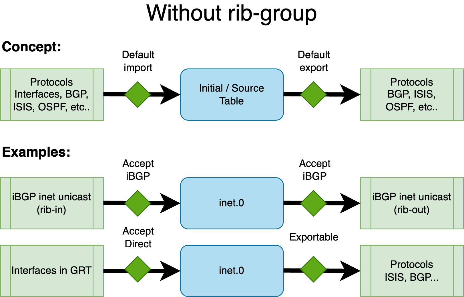
As shown above, for BGP with the inet family (IPv4 unicast), the default routing table in the global context is inet.0 — both for importing and exporting routes. Similarly, interface IPv4 addresses (direct routes) in the global context also reside in inet.0.
To leak routes from one table to another, the RIB group feature is employed, configured under routing-options. A RIB group is defined with the following parameters:
1 2 3 4 5 6 7 8 | |
Note:
import-policyandexport-policyare optional, but at least one destination table must be specified inimport-rib.
The import-rib statement is crucial. The order of tables matters: the first table is the source (or initial, standard, contributing) table. This is the default RIB associated with a given protocol/family combination. With a RIB group, routes are taken from this source table and replicated into one or more destination tables.
The RIB group establishes a link between the source RIB and the destination RIBs. The import-policy provides fine-grained control, allowing only specific routes or protocols to be leaked to the destination tables. Similarly, export-policy controls which routes from the destination tables are eligible for export by routing protocols.
The next figure illustrates the concept:
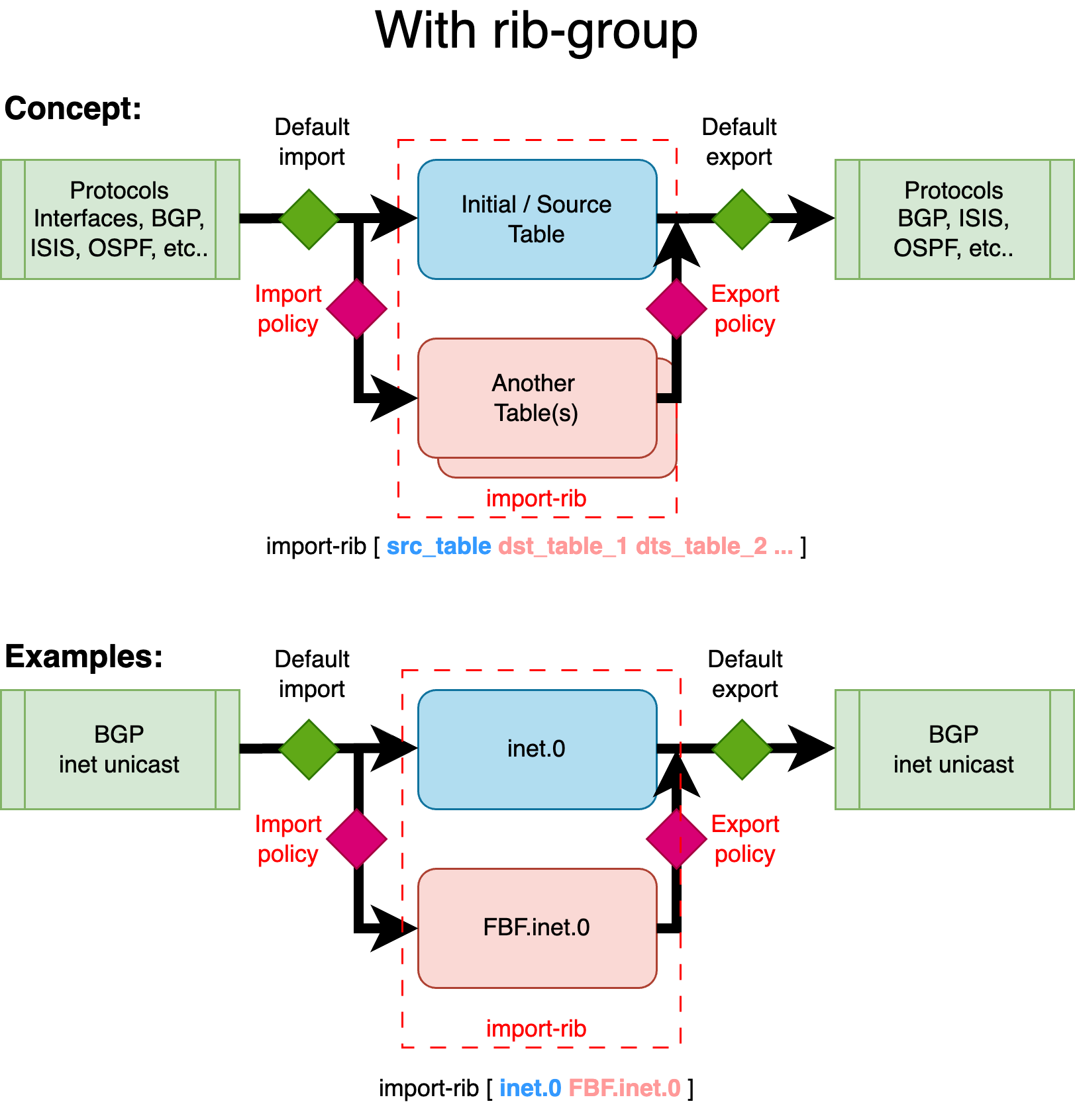
This example demonstrates how BGP unicast routes from the global routing context are leaked into a new routing table (or instance) called FBF. While these routes remain in their default (source) table — inet.0 — they are also copied into an additional table, in this case, the destination FBF.inet.0, using a RIB group.
In the context of Filter-Based Forwarding (FBF), this allows you to constrain routing decisions to a specific set of routes — not by using the standard FIB, but by relying on a custom FIB built from the custom destination RIB. This destination RIB can be selectively populated with only the routes you want to use for FBF-based traffic steering.
Let's illustrate this second FBF method with an example.
3.2. Example 2 - Topology
The Device Under Test (DUT) is an MX480 equipped with an MPC10E line card.
This simplified setup represents a typical DCI router connected to an IP Fabric, providing access to remote resources via two distinct paths:
- A quality path through an MPLS/SR core network, and
- A best-effort path via a direct peering or transit (PNI) connection.
In this scenario, remote resources are reached via the direct PNI link connected in the Global Routing Table (GRT) and sent from the peer to our DUT via an eBGP session. The DUT also receives the same remote resources from a remote ASBR through an iBGP session. The remote ASBR sets the next-hop address of these routes with its Segment Routing node-SID (advertised in the ISIS SR domain). This allows for a BGP Free-core by tunneling traffic in a transport SR tunnel.
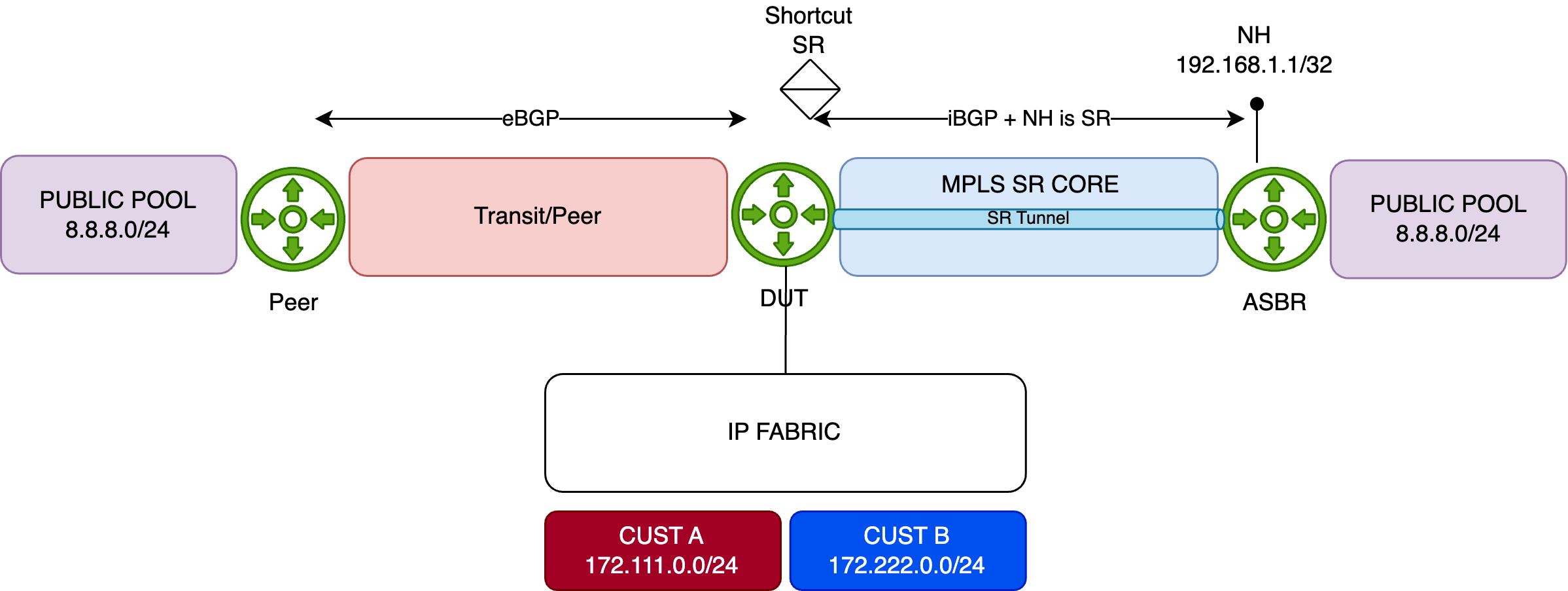
For demonstration purposes, the remote resource is simulated using the public prefix 8.8.8.0/24. This prefix is preferred by default via the direct PNI, with a backup path available through the MPLS/SR core (shortcut SR):
1 2 3 4 5 6 7 8 9 10 11 | |
Initial Configuration
Below is the initial configuration for the DUT, kept simple for clarity:
- The DUT receives customer prefixes via eBGP from the peer group FABRIC.
- The DUT receives public prefixes from the PNI peer—this is the primary/best path. A higher local-preference is set using the
PREFimport policy. - It also receives public prefixes from the peer ASBR via iBGP—this is a backup path—remotely reachable through an MPLS SR Tunnel.
1 2 3 4 5 6 7 8 9 10 11 12 13 14 15 16 17 18 19 20 21 22 23 24 25 26 27 28 29 | |
Configuration of FBF
The next steps involve creating a new routing instance (type forwarding) and leaking both the interface routes (i.e., direct routes for resolving the Layer 2 header) and the remote resources (in our case, 8.8.8.0/24), but only those announced by the core network - not those learned via the PNI.
First, create the FBF routing instance:
1 2 3 4 5 6 7 8 9 10 | |
Next, create a new rib-group called RG_FBF, establishing a relationship between the inet.0 table and FBF.inet.0. In other words, a relation between the default IPv4 table and the IPv4 table of our newly created FBF routing instance.
1 2 3 4 5 6 7 8 9 10 11 12 | |
Remember, the order inside the import-rib option is important. The first table is considered the source table, and the second one is the destination table. At this point, nothing is leaked between these two tables; this configuration merely establishes the relationship.
The first routes to leak are the direct interfaces attached to inet.0. This can be achieved with the following configuration under routing-options:
1 2 3 4 5 6 7 8 9 10 | |
Once committed, you should see direct and local routes in the FBF.inet.0 table. Verify with:
1 2 3 4 5 6 7 8 9 10 11 12 13 14 15 16 17 18 19 | |
Everything looks good so far. The next step is to leak some BGP routes into the FBF routing table. But which ones?
Our goal is to redirect traffic entering this forwarding instance along a specific path — the one advertised by our remote ASBR. This route is available in the default inet.0 table as a backup path. To achieve this, we'll configure BGP to use the RG_FBF rib-group. This rib-group allows routes normally imported into inet.0 to be simultaneously leaked into FBF.inet.0.
Let’s apply this on the ASBR peer-group:
1 2 3 4 5 6 7 8 9 10 11 12 13 14 15 16 17 18 | |
With this configuration, all routes received from this peer-group will be leaked into FBF.inet.0. However, for demonstration purposes, we’ll restrict the leaking to a specific BGP prefix: 8.8.8.0/24.
To do that, we’ll use the import-policy feature of the rib-group. First, we define a policy to authorize leaking from inet.0 to FBF.inet.0, but only for:
- direct routes, and
- the BGP prefix 8.8.8.0/24
Here’s the policy definition, followed by its application to the RG_FBF rib-group:
1 2 3 4 5 6 7 8 9 10 11 12 13 14 15 16 17 18 19 20 21 22 23 24 25 26 27 28 29 30 31 32 | |
After committing, you can verify the result with:
1 2 3 4 5 6 7 8 | |
Perfect — only the 8.8.8.0/24 prefix received from the internal ASBR is installed. The primary route via the PNI isn't present in this instance and remains solely in the inet.0 table.
Now, to actually redirect the traffic, we’ll use a simple firewall filter. It will match traffic sourced from Customer B and redirect it to the FBF routing instance. This filter is applied to the physical interface connected to the IP Fabric:
1 2 3 4 5 6 7 8 9 10 11 12 13 14 15 16 17 18 19 20 21 22 23 24 25 26 27 28 29 30 31 32 33 34 35 36 37 38 39 40 41 42 | |
At this point, traffic should be redirected as expected:
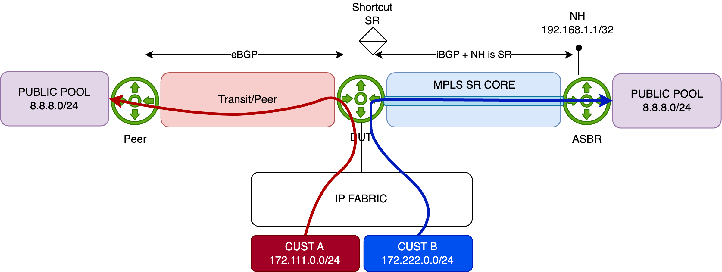
To help distinguish the flows, we've configured traffic rates as follows:
- Customer A: 1000 packets per second (pps)
- Customer B: 5000 packets per second (pps)
Let’s monitor the PNI interface. As expected, only Customer A traffic goes through it (1000pps):
1 2 3 4 5 6 7 8 9 10 | |
Now let’s check the core-facing interface — we can see Customer B’s traffic being redirected via FBF to the ASBR:
1 2 3 4 5 6 7 8 9 10 | |
Now, what if the iBGP session to the ASBR drops, or the 8.8.8.0/24 prefix is no longer announced?
In that case, the route will vanish from FBF.inet.0, and the default reject route will take over:
1 2 3 4 5 | |
Just like in Case 1, traffic to 8.8.8.0/24 will be rejected and punted to the routing engine (RE), which will respond with ICMP Unreachable messages (after being HW-policed to 2k pps).
To silently drop such packets instead of punting them, configure a static discard route as the default inside the FBF instance. But what if you want a fallback to the default routing table instead?
That’s simple. If fallback forwarding is needed, just configure a default route inside the FBF instance pointing to the inet.0 table. If 8.8.8.0/24 disappears, traffic is then forwarded via the primary PNI path through inet.0.
Here’s the configuration:
1 2 3 4 5 6 7 8 9 10 11 12 13 14 15 | |
3.3. PFE analysis
Assuming the FBF configuration is active, let’s break down how the firewall filter behaves at the PFE level. Start by listing the filter instances:
1 2 3 4 5 6 | |
Next, pick up the InstanceToken and resolve it using the following command:
1 2 3 4 5 6 7 8 9 10 11 12 13 14 15 16 17 18 19 20 21 22 23 24 25 26 27 28 29 30 31 32 33 34 35 | |
Focus on the Action NH (line 17) and decode the JNH word. As shown, this represents a chain of Next-hops:
The parameter
instbelow refers to the PFE id.
1 2 3 4 5 | |
Now let’s analyze the third action by decoding the JNH word 0x20129a4c0000000c - UcodeNH will execute a micro-code sequence:
1 2 | |
This is an indirection to a virtual address found in the Next field. To read data at 0x4a693, use:
1 2 | |
This yields two important values:
- Paddr (physical address):
0x104a693 - Data read:
0x0812944c00020000
Note: to read a physical address, use
show pread paddr xxx.
Since this is a JNH word, decode it again:
1 2 3 4 5 | |
Now decode each action (except the third one - out of the scope of this article):
- First is a
ModifyNH(we modify some bytes of the Local Memory - here we reset en encap len)
1 2 3 | |
- Second points to another JNH word
0x1810318100200008- This one is a CallNH which means execute a list of NH in order (whenmode=O):
1 2 3 | |
Decode the first and single NH in the list, 0x1810318100200008 to reveal a KTREE structure used for route lookup:
A KTREE is the Juniper implementation of a standard binary structure known as Patricia Tree
1 2 | |
Use additional options to dump the full KTREE:
1 2 3 4 5 6 7 | |
This KTREE acts as the FIB for our FBF routing-instance. For example, if traffic hits the 8.8.8.0/24 prefix, it’s "redirected" to the action identifed by the JNH word 0x0812a04000000000 which refers to a list of NH (CallNH):
1 2 3 | |
Whose the value 0x2012a0a40000000c refers to indirection - UcodeNH:
1 2 | |
To read this NH indirection at the virtual address 0x4a829:
1 2 | |
One mmore time, we decode the JNH word retrieved from the previous virtual memory address - and we find out a new list of NH (CallNH):
1 2 3 | |
And decode 0x11c0000000038d14:
1 2 3 | |
We’ve reached the final forwarding result — which will set the forwarding NH index into the NH Token. Here, the token 0x38d corresponds to the NH ID of our lookup result.
You can get more info on this NH:
1 2 3 | |
Perfect — this matches expectations. Traffic targeting 8.8.8.0/24 via the FBF routing instance will be forwarded to the core interface et-5/0/0.0.
You can dig deeper using this detailed view (to retrieve Layer 2 header information, MPLS encap...)
1 2 3 4 5 6 7 8 9 10 11 12 13 14 15 16 17 18 19 20 21 22 23 24 25 26 27 28 29 30 31 32 33 34 35 36 37 38 39 40 41 42 43 44 45 46 47 48 49 | |
If we repeat the exercise with the 8.8.8.0/24 prefix no longer present in the FBF.inet.0 table, any traffic destined for 8.8.8.0/24 will match the default 0/0 route, which redirects to the inet.0 table via a next-table action. In this scenario, we would notice slightly longer processing — just a few extra instructions — due to the need for two lookups:
- The first lookup occurs in the FBF FIB instance, which triggers the next-table action and redirects the processing to the main IPv4
inet.0table, - The second lookup happens in the
inet.0FIB, where the best route to 8.8.8.0/24 is selected—in our case, through interface et-2/0/0.0, which connects to our PNI.
In this situation, two KTREE structures are involved: first the
FBF.inet.0KTREE, followed by theinet.0KTREE.
and another table - just for illustration
| PFE COMPLEX | Port Number | 10GE mode |
|---|---|---|
| EA ASIC 0 | 0 | xe-0/1/0 |
| 1 | xe-0/1/1 | |
| 2 | xe-0/1/2 | |
| 3 | xe-0/1/3 | |
| 4 | xe-0/1/4 | |
| 5 | xe-0/1/5 | |
| 6 | xe-0/1/6 | |
| 7 | xe-0/1/7 |
Table 3: Interface Naming of the 8xSFP+ PIC
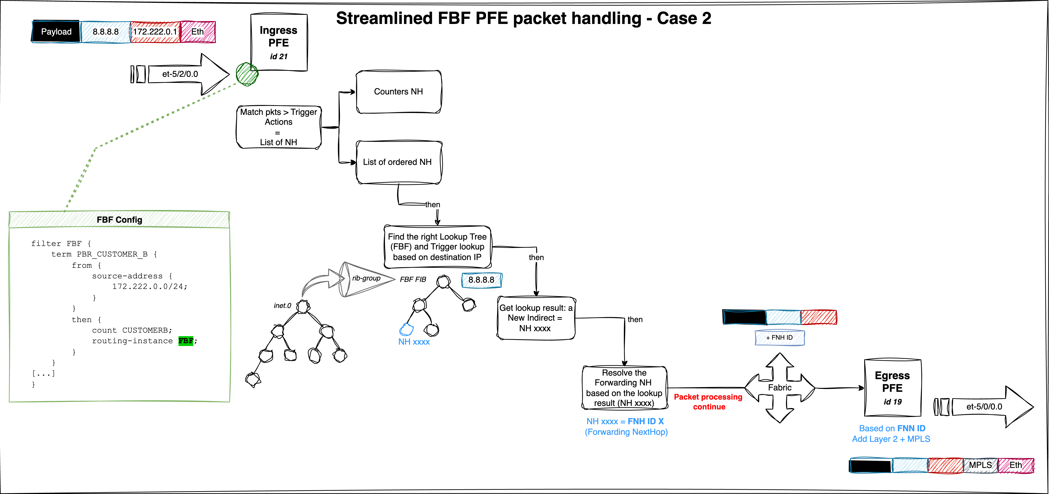
The following figure provides a consolidated view of the packet traversal process and outlines the key steps of the FBF mechanism:
This is a test to refer to this section
3.4. Conclusion
In this article, we explored the mechanics of the Filter-Based Forwarding (FBF) feature, focusing on how traffic steering is implemented at the PFE level. We demonstrated two distinct approaches to configuring and validating FBF behavior. While both are effective, the second method provides greater flexibility, making it especially useful for advanced use cases.
All tests and examples provided were conducted within the IPv4 address family, but it's important to highlight that the same FBF logic and infrastructure are fully supported for IPv6 as well, offering consistent behavior across protocol versions.
By understanding the inner workings of FBF down to the hardware abstraction layer, network engineers can confidently design and validate sophisticated traffic steering policies.